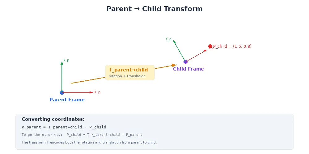
Building a Transform Tree
A robot with 20 sensors, 10 joints, and 4 wheels might have 50+ coordinate frames. Tracking the transform between every pair would mean storing 50 × 49 = 2,450 transforms. That's not sustainable.
Instead, we use a transform tree — a hierarchical structure where each frame has one parent, and transforms are stored only between parent and child. The system computes any frame-to-frame transform by walking the tree.
The Structure
A transform tree looks like this:
Each arrow represents a stored transform. We store:
world → base_link(robot's position in the world)base_link → camera_link(camera's position on the robot)camera_link → camera_optical_frame(sensor coordinate convention)base_link → lidar_link- ... and so on
Total: 9 transforms stored (one per edge), not 2,450.
Parent-Child Relationships
The key rule: each frame has exactly one parent (except the root, which has no parent).
When you define a frame, you specify its parent:
# Root frame (no parent)
tf_tree.add_frame("world")

# Robot base is a child of world
tf_tree.add_frame("base_link", parent="world")

# Camera is a child of base_link
tf_tree.add_frame("camera_link", parent="base_link",
                  translation=(0.1, 0, 0.3),  # 10cm forward, 30cm up
                  rotation=(0, 0, 0))         # No rotation

# Camera optical frame is a child of camera_link
tf_tree.add_frame("camera_optical_frame", parent="camera_link",
                  translation=(0, 0, 0),
                  rotation=(0, -90, 0))       # -90° pitch (standard convention)
This creates the parent-child relationships. The transform tree now knows:
- To go from
worldtocamera_link, go throughbase_link - To go from
camera_optical_frametoworld, go backward throughcamera_link, thenbase_link, thenworld
Looking Up Transforms
Now the magic: you can ask for the transform between any two frames, even if they're not directly connected.
# Direct parent-child transform (stored)
T = tf_tree.lookup_transform("base_link", "camera_link")

# Indirect transform (computed by walking the tree)
T = tf_tree.lookup_transform("world", "camera_optical_frame")
# Walks: world → base_link → camera_link → camera_optical_frame

# Sibling frames (walk up, then down)
T = tf_tree.lookup_transform("camera_link", "lidar_link")
# Walks: camera_link → base_link (up), then base_link → lidar_link (down)
The tree system figures out the path automatically.
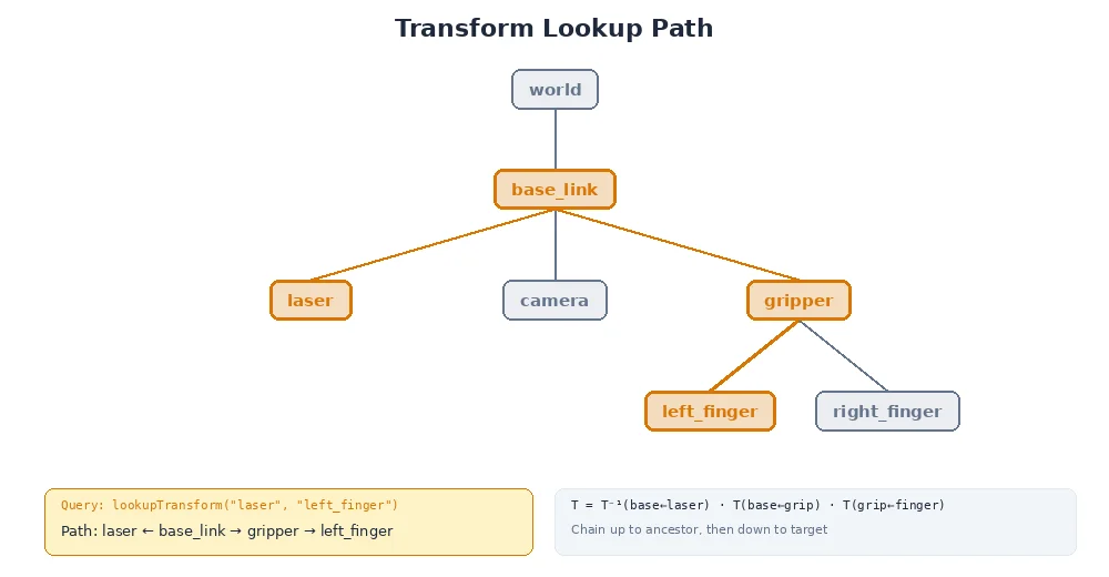
The Algorithm
Here's how transform lookups work:
- Find the common ancestor of the source and target frames
- Walk up from source to ancestor, collecting inverse transforms
- Walk down from ancestor to target, collecting forward transforms
- Multiply all transforms together
This is why the tree structure is so efficient. To compute camera → gripper, we don't need a direct transform. We walk up from camera to base_link, then down from base_link to gripper. The tree guarantees there's always a path.
Example Walkthrough
Let's compute the transform from camera_optical_frame to gripper_link:
Camera path to root:
  camera_optical_frame → camera_link → base_link

Gripper path to root:
  gripper_link → arm_link_2 → arm_link_1 → arm_base → base_link

Common ancestor: base_link

Forward path (camera to base_link):
  camera_optical_frame → camera_link → base_link
  T1 = T(cam_opt → cam_link) * T(cam_link → base_link)

Backward path (base_link to gripper):
  base_link → arm_base → arm_link_1 → arm_link_2 → gripper_link
  T2 = T(base_link → arm_base) * T(arm_base → link1) * T(link1 → link2) * T(link2 → gripper)

Combined:
  T(camera → gripper) = T1 * T2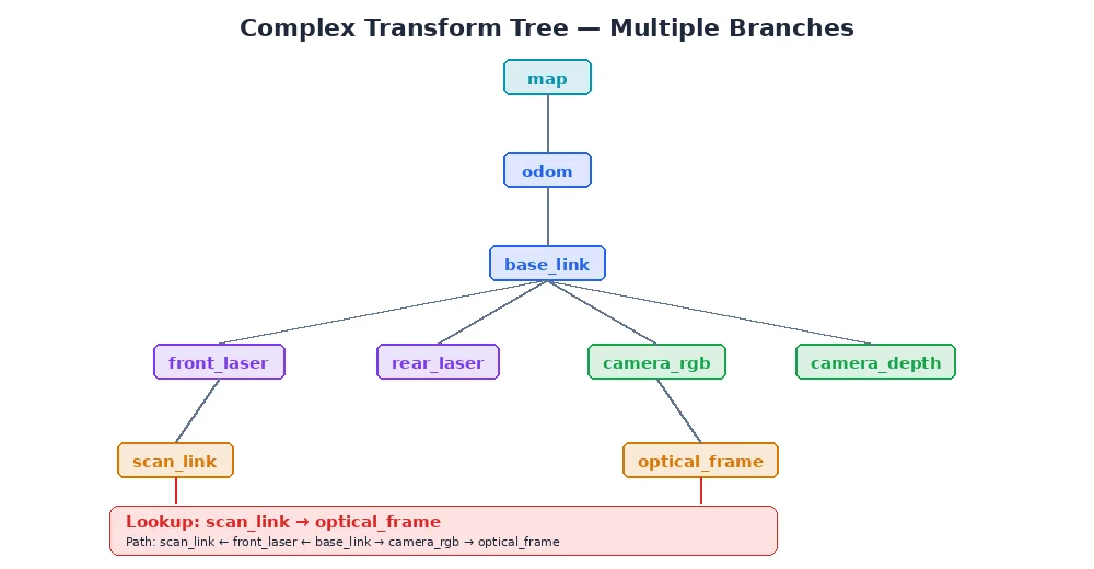
Why a Tree, Not a Graph?
Why does each frame have exactly one parent? Why not allow multiple parents?
Answer: to avoid ambiguity. If camera_link had two parents (base_link and head_link), there would be two paths to reach it from world:
world → base_link → camera_linkworld → base_link → head_link → camera_link
Which one is correct? The tree structure enforces a single, unambiguous path.
If you have multiple paths in your physical robot (e.g., a closed kinematic chain like a parallel robot), you model it as a tree by choosing one path as "primary" and computing the others as constraints. Most robots are naturally tree-structured anyway.
Dynamic Frames
Not all frames are fixed. The robot moves in the world. Arm joints rotate. Wheels turn.
The transform tree handles this by allowing frames to update their parent transform over time.
# Initially, robot is at origin
tf_tree.update_transform("base_link", "world",
                         translation=(0, 0, 0),
                         rotation=(0, 0, 0),
                         timestamp=now())

# Robot moves forward 1 meter
tf_tree.update_transform("base_link", "world",
                         translation=(1, 0, 0),
                         rotation=(0, 0, 0),
                         timestamp=now() + 1.0)

# Arm joint rotates 45°
tf_tree.update_transform("arm_link_2", "arm_link_1",
                         translation=(0, 0, 0.3),  # Fixed link length
                         rotation=(0, 0, 45),      # Joint angle changed
                         timestamp=now() + 1.0)
When you look up a transform, the tree uses the most recent update. In the next lesson, we'll cover how systems handle transforms that vary over time.
What's Next?
You've learned how to organize frames into a tree. But we've been glossing over one detail: how exactly do we represent rotations? In the next lesson, we'll tackle quaternions — the standard (and somewhat magical) way to store and interpolate 3D rotations.