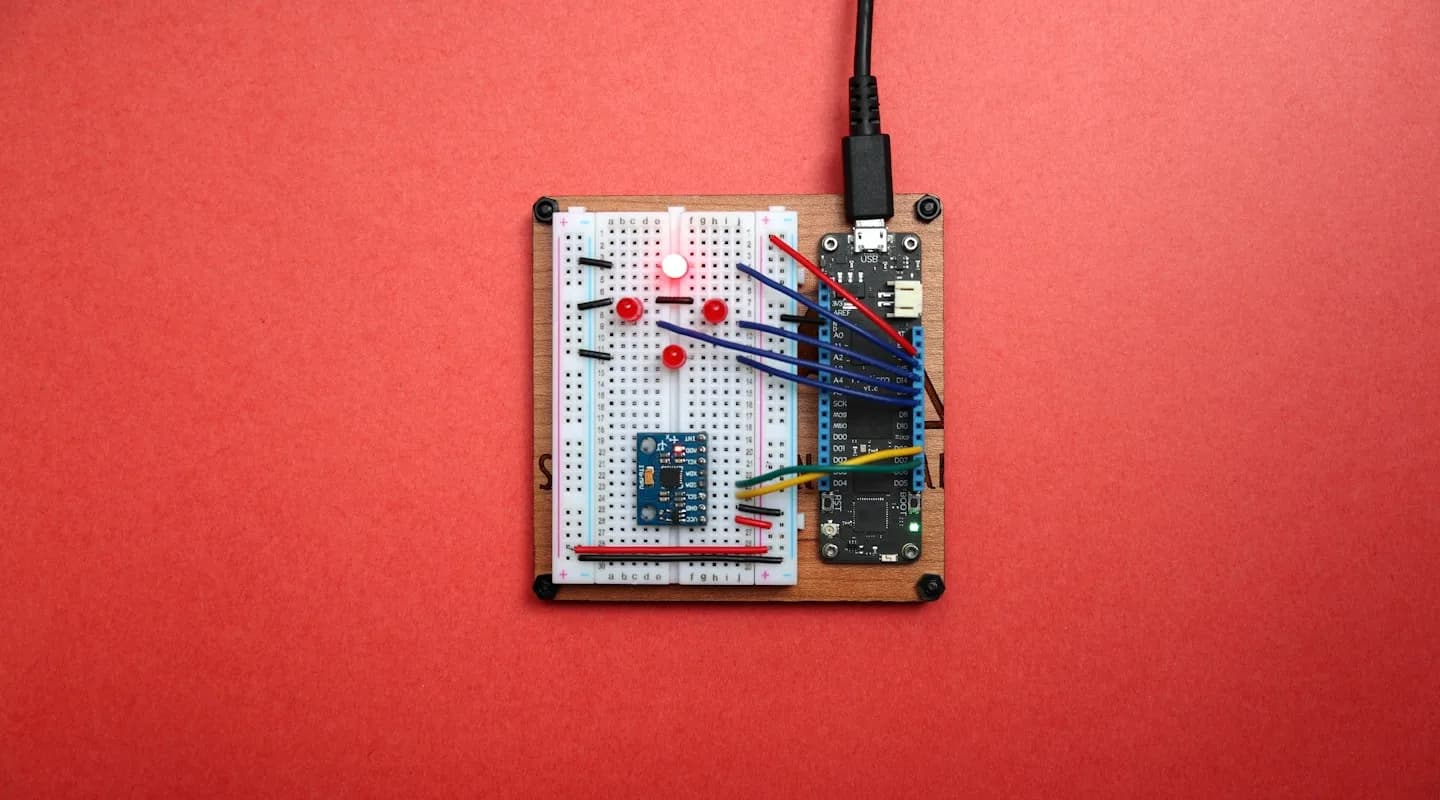
Camera Basics
Cameras are the most common sensor in robotics. They're cheap, information-dense, and versatile. But to use them well, you need to understand what they actually do: turn 3D scenes into 2D images.
The Pinhole Camera Model
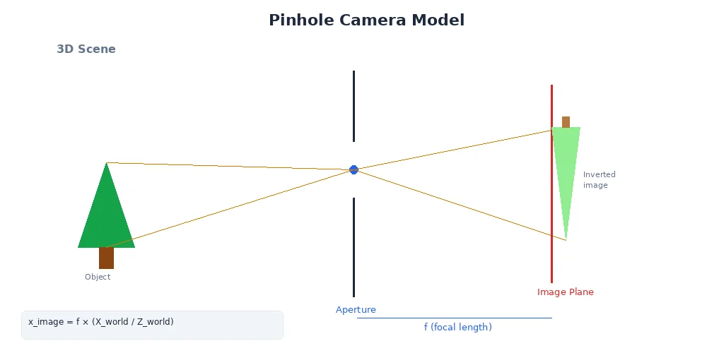
Imagine a dark box with a tiny hole on one side. Light from the world passes through the hole and projects an image on the opposite wall. That's a pinhole camera — and it's how all cameras fundamentally work.
The math is surprisingly simple:
x_image = f * (X_world / Z_world)
y_image = f * (Y_world / Z_world)
Where:
(X, Y, Z)is a point in the 3D world(x, y)is where it lands on the 2D imagefis the focal length — the distance from the hole to the image plane
The focal length determines the field of view. A small focal length (wide-angle lens) sees more of the world but with more distortion. A large focal length (telephoto lens) sees a narrow slice with less distortion.
Image Formation
When light hits the image sensor (or film), it's recorded as a grid of pixels.
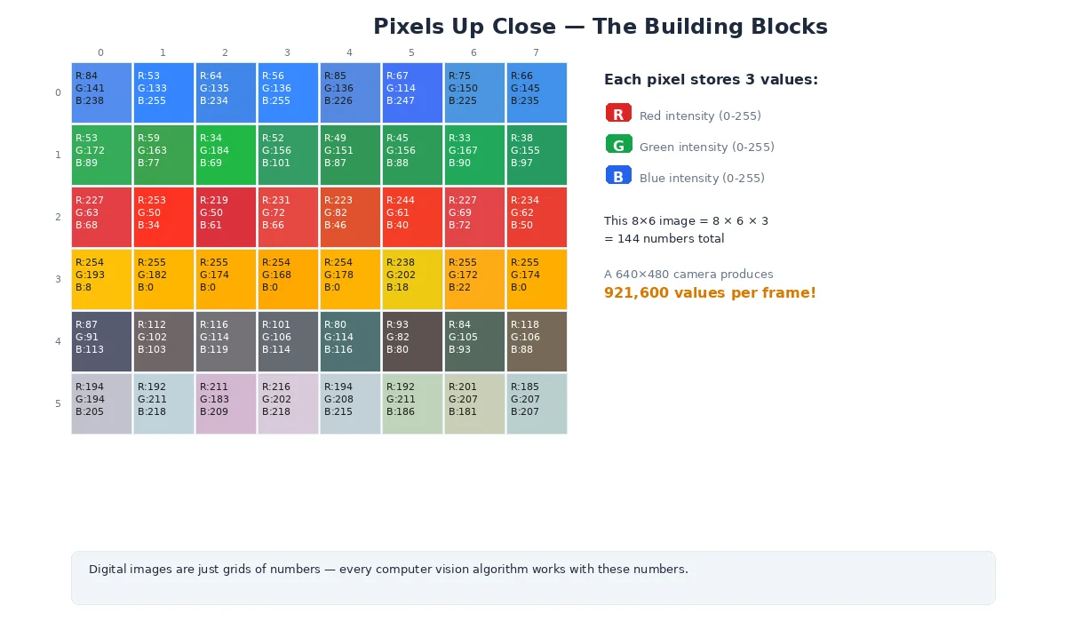
Each pixel stores:
- Grayscale: One intensity value (0 = black, 255 = white for 8-bit)
- Color (RGB): Three values — red, green, blue intensities
- Depth: Distance to the object (if using a depth camera)
# A 640x480 RGB image
width = 640   # pixels
height = 480  # pixels
channels = 3  # Red, Green, Blue

# Total data: 640 * 480 * 3 = 921,600 bytes (~1MB per frame)
# At 30 FPS, that's 30MB/sec of raw image data!

# Accessing a pixel at (x=100, y=200):
pixel = image[200, 100]  # Note: row (y) comes first
red = pixel[0]
green = pixel[1]
blue = pixel[2]
Resolution and Field of View
Two critical camera parameters:
Resolution
How many pixels fit in the image. Common sizes:
- VGA: 640×480 (0.3 megapixels)
- HD (720p): 1280×720 (0.9 megapixels)
- Full HD (1080p): 1920×1080 (2.1 megapixels)
- 4K: 3840×2160 (8.3 megapixels)
Higher resolution = more detail, but also more data to process.
Field of View (FOV)
How much of the world the camera sees, measured in degrees:
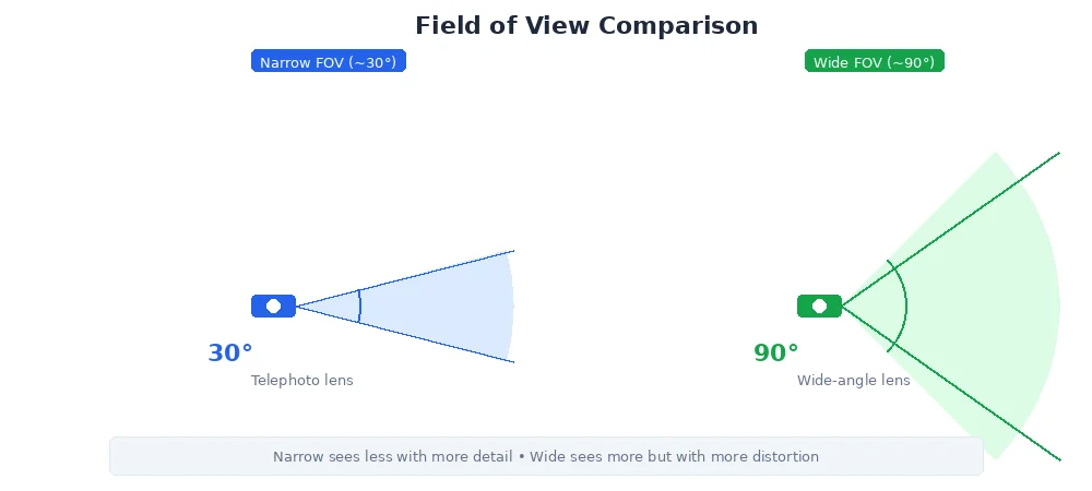
- Narrow (~30°): Telephoto lens, good for distant objects
- Normal (~60°): Similar to human vision
- Wide (~90°+): Wide-angle lens, sees more but with barrel distortion
For robots navigating tight spaces (warehouses, homes), wide FOV is critical — you need to see obstacles to the sides. For inspection tasks (reading gauges, spotting defects), narrow FOV with high resolution works better.
Lens Distortion
Real lenses aren't perfect pinholes. They introduce distortion:
Radial Distortion
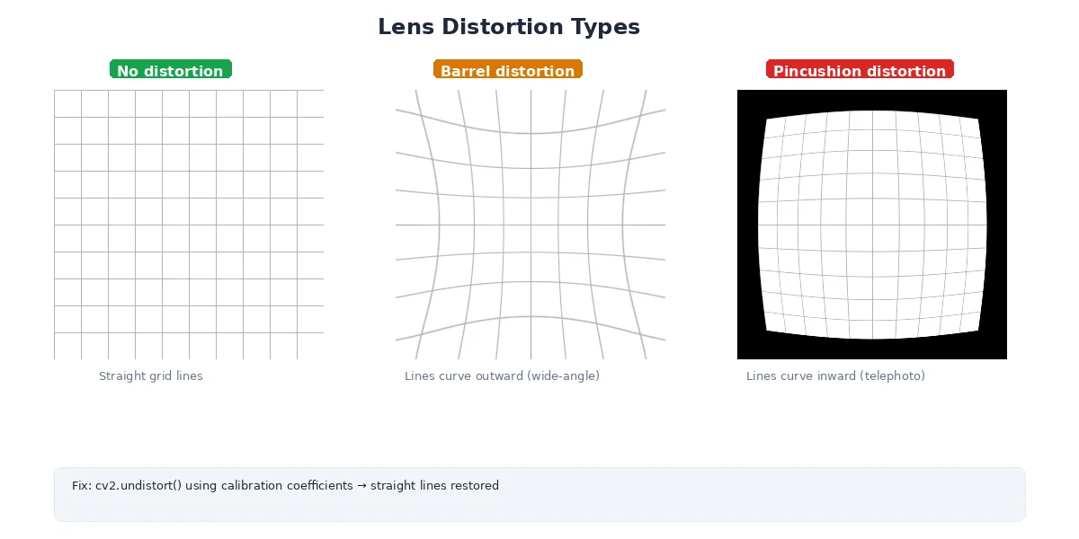
- Barrel distortion: Straight lines curve outward (common in wide-angle lenses)
- Pincushion distortion: Straight lines curve inward (common in telephoto lenses)
Tangential Distortion
The lens isn't perfectly aligned with the sensor — images look slightly tilted.
Why It Matters
If you're measuring distances or building 3D maps, distortion throws off your calculations. A straight wall looks curved in the image. Solution: camera calibration.
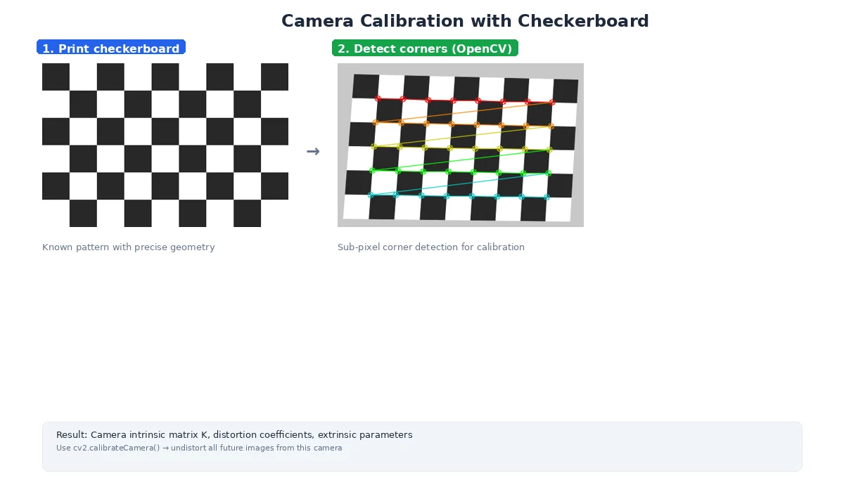
Camera Calibration
Calibration figures out:
- Intrinsic parameters: focal length, optical center, distortion coefficients
- Extrinsic parameters: where the camera is positioned and oriented in 3D space
The process:
- Print a checkerboard pattern
- Take 10-20 images from different angles
- Software detects corners and computes distortion
- Store the camera matrix and distortion coefficients
# Intrinsic Matrix (K)
# Describes the camera's internal geometry
K = [
  [fx,  0, cx],  # fx = focal length in pixels (x-axis)
  [ 0, fy, cy],  # fy = focal length in pixels (y-axis)
  [ 0,  0,  1]   # cx, cy = optical center (image center)
]

# Distortion Coefficients
# Corrects for lens imperfections
dist = [k1, k2, p1, p2, k3]
#      ^   ^   ^   ^   ^
#      |   |   |   |   |
#      radial  |   tangential
#              radial (higher order)
What's Next?
Cameras give us 2D images, but robots need to understand distance. In the next lesson, we'll explore LiDAR — a sensor that directly measures 3D geometry by shooting lasers at the world.