Tuning & Debugging
You built a PID controller, picked some gains, and hit run. Your robot lurches forward, overshoots the target, wobbles, and eventually settles -- kind of. Or maybe it just vibrates in place. Now what?
This lesson is about the practical side: how to systematically tune PID gains, how to read the signs when something is wrong, and how to use logging and testing to prove your controller actually works.
Manual Tuning: The Step-by-Step Method
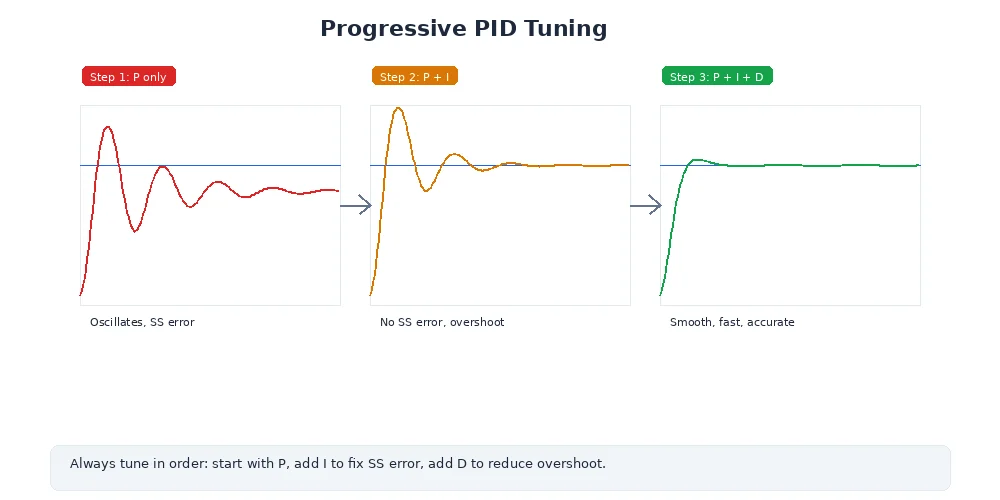
If you have no idea where to start, follow this sequence. It works for nearly every system.
Step 1. Set Kp = 0, Ki = 0, Kd = 0. The robot should not move.
Step 2. Increase Kp slowly. Command a step change (e.g., target speed jumps from 0 to 1.0 m/s). Watch the response:
- Too low: the robot barely moves.
- Good: the robot reaches the target quickly but overshoots a little.
- Too high: the robot oscillates and never settles.
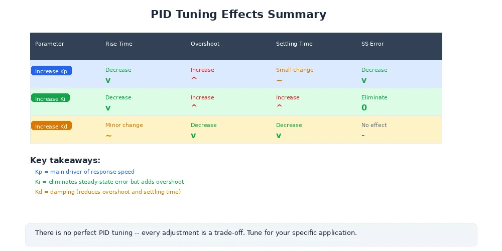
Stop when you see sustained oscillation (constant back-and-forth). Note this critical gain as Ku, then set Kp = 0.5 * Ku.
Step 3. If the robot settles close to the target but not exactly on it (steady-state error), increase Ki in small increments until the error disappears. Use the minimum Ki that works.
Step 4. If overshoot is a problem, increase Kd to add damping. Go slowly -- too much Kd amplifies sensor noise and causes jitter.
Most wheeled robots work well with just PI control (Kd = 0). Only add the D term if you see persistent overshoot that the P and I terms cannot solve alone.
Ziegler-Nichols: A Classic Starting Point
The Ziegler-Nichols method gives you a formula-based starting point. It is not magic -- you will still need to refine the results -- but it gets you in the right ballpark.
- Set
Ki = 0andKd = 0. - Increase
Kpuntil the system oscillates continuously at a constant amplitude. This is the ultimate gainKu. - Measure the oscillation period
Tu(seconds for one full cycle).
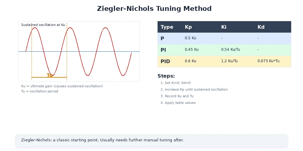
- Apply the formulas:
| Controller | Kp | Ki | Kd |
|---|---|---|---|
| P only | 0.5 * Ku | 0 | 0 |
| PI | 0.45 * Ku | 1.2 * Kp / Tu | 0 |
| PID | 0.6 * Ku | 2 * Kp / Tu | Kp * Tu / 8 |
For example, if Ku = 4.0 and Tu = 0.4 s:
Kp = 0.6 * 4.0 = 2.4Ki = 2 * 2.4 / 0.4 = 12.0Kd = 2.4 * 0.4 / 8 = 0.12
Ziegler-Nichols was designed for slow industrial processes and often produces aggressive gains for fast mechanical systems. Treat the output as a starting point, then reduce Ki and Kd if the response is too aggressive.
Diagnosing Common Problems
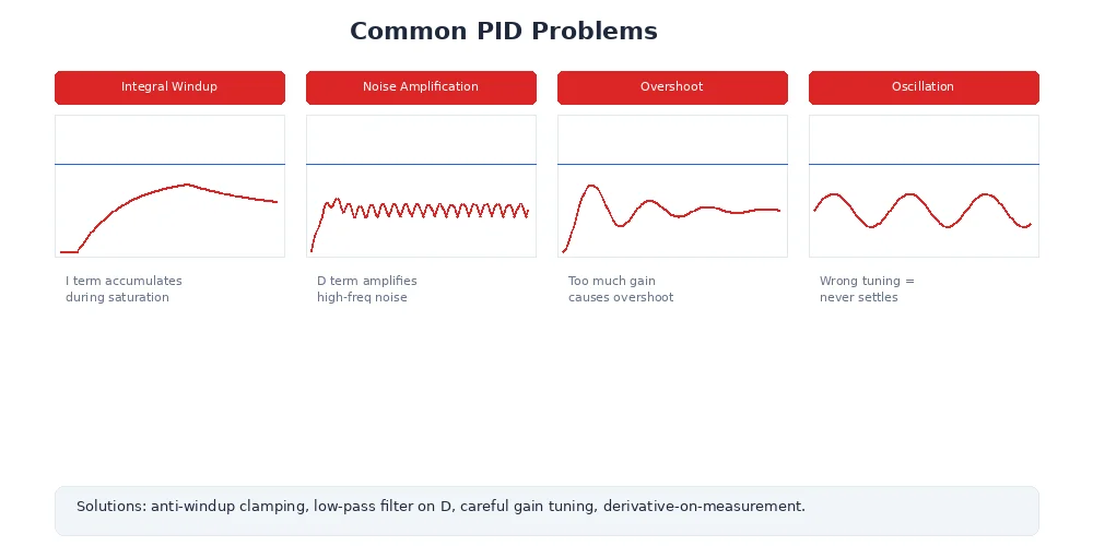
When your robot misbehaves, the symptom tells you which gain to adjust.
| Symptom | Likely Cause | Fix |
|---|---|---|
| Oscillates around the target | Kp too high | Lower Kp, or increase Kd to add damping |
| Overshoots then slowly settles | Kp slightly too high, Kd too low | Lower Kp or raise Kd |
| Settles below the target (steady-state error) | Ki too low or zero | Increase Ki gradually |
| Very slow to reach the target | Kp too low | Increase Kp |
| Jitters and twitches near the target | Kd too high, amplifying sensor noise | Lower Kd, or filter sensor data |
| Shoots forward after being stuck | Integral windup | Add anti-windup (clamp the integral term) |
class PIDController:
    def __init__(self, Kp, Ki, Kd, max_integral=10.0):
        self.Kp = Kp
        self.Ki = Ki
        self.Kd = Kd
        self.max_integral = max_integral
        self.integral = 0.0
        self.prev_error = 0.0

    def update(self, target, actual, dt):
        error = target - actual

        # Proportional
        P = self.Kp * error

        # Integral with anti-windup clamp
        self.integral += error * dt
        self.integral = max(-self.max_integral,
                           min(self.max_integral, self.integral))
        I = self.Ki * self.integral

        # Derivative (on error)
        D = self.Kd * (error - self.prev_error) / dt
        self.prev_error = error

        return P + I + D
Using Logs and Plots to Debug
Staring at a moving robot and guessing what is wrong is a losing strategy. Instead, log the data and plot it.
Record these values every control loop iteration:
- Timestamp -- so you can see timing.
- Target (setpoint) -- what you asked for.
- Actual (measurement) -- what the sensor reported.
- Error -- the difference.
- P, I, D terms -- the individual contributions.
- Total output -- what was sent to the motor.
import csv

log_file = open("pid_log.csv", "w", newline="")
writer = csv.writer(log_file)
writer.writerow(["time", "target", "actual", "error", "P", "I", "D", "output"])

t = 0.0
while t < 10.0:
    actual = sensor.read()
    error = target - actual

    P = pid.Kp * error
    I = pid.Ki * pid.integral
    D = pid.Kd * (error - pid.prev_error) / dt
    output = pid.update(target, actual, dt)

    writer.writerow([f"{t:.3f}", target, f"{actual:.4f}",
                     f"{error:.4f}", f"{P:.4f}", f"{I:.4f}",
                     f"{D:.4f}", f"{output:.4f}"])

    motor.set_power(output)
    t += dt

log_file.close()
Plot the CSV and look for these patterns:
- Target vs. Actual diverging: your gains are too low overall.
- Actual oscillating around Target:
Kptoo high orKdtoo low. - I term growing without bound: you need anti-windup.
- D term spiking wildly: sensor noise -- add a low-pass filter.
- Actual never reaching Target: steady-state error, increase
Ki.
A single plot of target vs. actual over time will tell you more in ten seconds than ten minutes of watching the robot.
Testing Strategies
Do not declare your controller "tuned" until you have tested it properly. Here are three tests every PID controller should pass.
1. Step Response Test
Command a sudden change in setpoint (e.g., target speed jumps from 0 to 1.0 m/s). Measure:
- Rise time: how quickly the actual value reaches 90% of the target.
- Overshoot: how far past the target the actual value goes (ideally under 10%).
- Settling time: how long until the actual value stays within 2% of the target.
2. Tracking Test
Command a smoothly changing setpoint (e.g., a sine wave or ramp). Check that the actual value follows the target closely without lagging behind. Large tracking error means your gains are too low or your control loop is too slow.
3. Disturbance Rejection Test
While the robot is holding a steady setpoint, apply a disturbance -- push the robot, add weight, or change the surface. The controller should recover quickly. If it takes a long time to return to the target, increase Ki. If it oscillates after the disturbance, increase Kd or lower Kp.
What's Next?
You now have the complete toolkit for precise robot motion: closed-loop feedback, PID algorithms, motor control modes, velocity commands, and practical tuning and debugging techniques.
In Module 6, we shift from motion to perception -- how robots see and understand the world using cameras, lidar, and sensor fusion. Because even a perfectly tuned controller is useless if the robot does not know where it is going.