Motor Control
You've got a motor. You want it to spin. But how you want it to spin depends on your task:
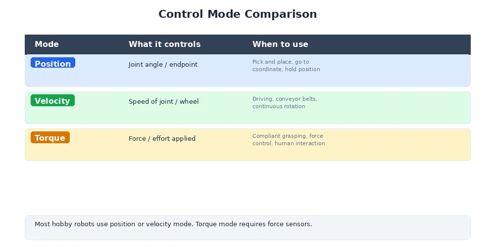
- Velocity control: "Spin at 100 RPM" (e.g., a conveyor belt, a fan)
- Position control: "Turn to 45 degrees" (e.g., a robot arm joint, a camera gimbal)
- Torque control: "Apply 2 Nm of force" (e.g., a robot gripper, a force-sensitive tool)
Each control mode uses different sensors, different control algorithms, and different ways of commanding the motor. Let's break them down.
The Three Control Modes
| Mode | You specify | Feedback sensor | Example use case |
|---|---|---|---|
| Velocity | Speed (RPM, rad/s) | Encoder or hall effect | Driving wheels, spinning propellers |
| Position | Angle (degrees, radians) | Encoder or potentiometer | Robot arm joints, steering servos |
| Torque | Force (Nm, A) | Current sensor | Grippers, compliant arms, haptic feedback |
Each mode builds on the last — position control often uses velocity control internally, and velocity control uses torque (current) control at the lowest level.
Velocity Control: Constant Speed
Goal: Make the motor spin at a target speed, regardless of load.
You use a PID controller with an encoder as the feedback sensor.
class VelocityController:
    def __init__(self, motor, encoder):
        self.motor = motor
        self.encoder = encoder
        self.pid = PIDController(Kp=1.5, Ki=0.3, Kd=0.05)

    def set_target_velocity(self, target_rpm):
        while True:
            # Measure actual speed
            actual_rpm = self.encoder.read_rpm()

            # PID computes motor power
            power = self.pid.update(
                target=target_rpm,
                actual=actual_rpm,
                dt=0.02
            )

            # Clamp power to valid range
            power = max(-1.0, min(1.0, power))

            # Send PWM signal to motor
            self.motor.set_pwm(power)

            time.sleep(0.02)  # 50 Hz control loop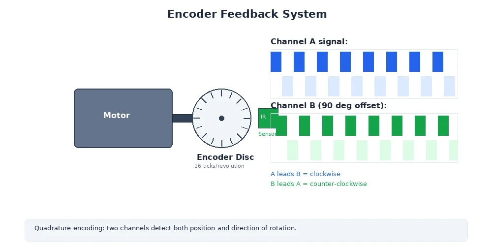
The PID controller adjusts motor power to maintain constant speed even if:
- The load changes (robot climbs a hill)
- The battery voltage drops
- Friction varies
This is the most common control mode for driving wheels.
Position Control: Move to a Target Angle
Goal: Rotate the motor to a specific angle and hold it there.
You still use a PID controller, but now the error is the difference in position, not velocity. And the output is often a velocity command to a lower-level velocity controller.
class PositionController:
    def __init__(self, motor, encoder):
        self.motor = motor
        self.encoder = encoder
        self.pid = PIDController(Kp=3.0, Ki=0.1, Kd=0.2)
        self.velocity_controller = VelocityController(motor, encoder)

    def move_to_position(self, target_angle):
        while True:
            # Measure current position
            actual_angle = self.encoder.read_angle()

            # PID computes desired velocity
            target_velocity = self.pid.update(
                target=target_angle,
                actual=actual_angle,
                dt=0.02
            )

            # Check if close enough
            error = abs(target_angle - actual_angle)
            if error < 0.5:  # Within 0.5 degrees
                self.velocity_controller.set_target_velocity(0)
                break

            # Send velocity command to lower-level controller
            self.velocity_controller.set_target_velocity(target_velocity)

            time.sleep(0.02)
This is a cascaded control design — position PID → velocity PID → motor PWM. Each layer of control handles one aspect of the motion.
Position control is essential for:
- Robot arms: Each joint must reach a precise angle
- Steering: Turn the wheels to a specific angle
- Servos: Camera gimbals, sensor platforms
In real robot arms, you often want to control the position of the end effector (the gripper or tool), not the individual joint angles. This requires inverse kinematics to compute which joint angles achieve the desired end position. We'll cover that in Module 7.
Torque Control: Apply a Specific Force
Goal: Make the motor apply a precise force, regardless of speed or position.
Torque is proportional to current in a DC motor (Torque = Kt × Current, where Kt is the motor's torque constant). So torque control is really current control.
class TorqueController:
    def __init__(self, motor, current_sensor):
        self.motor = motor
        self.current_sensor = current_sensor
        self.pid = PIDController(Kp=0.8, Ki=0.2, Kd=0.0)

    def set_target_torque(self, target_torque_nm):
        # Convert torque to current (motor's Kt constant)
        target_current = target_torque_nm / self.motor.torque_constant

        while True:
            # Measure actual current
            actual_current = self.current_sensor.read_current()

            # PID computes motor voltage
            voltage = self.pid.update(
                target=target_current,
                actual=actual_current,
                dt=0.001  # Fast loop (1 kHz) for current control
            )

            # Send voltage command to motor driver
            self.motor.set_voltage(voltage)

            time.sleep(0.001)
Torque control is critical for:
- Force-sensitive tasks: Polishing, assembly, medical robotics
- Compliant motion: The robot "gives" when it hits an obstacle
- Human-robot interaction: Collaborative robots (cobots) that are safe to touch
How Motors Actually Work: H-Bridge and PWM
Let's zoom down to the hardware level. How does your microcontroller actually control motor power?
The H-Bridge
An H-bridge is a circuit that lets you:
- Spin the motor forward (positive voltage)
- Spin the motor backward (negative voltage)
- Brake the motor (short the terminals)
- Let it coast (open circuit)
It's called an H-bridge because of the shape:
        +V
         │
    ┌────┼────┐
    │    │    │
   [S1] [S2] [S3] [S4]  ← Switches (transistors)
    │    │    │    │
    └────┼────┼────┘
         │    │
         M    M  ← Motor terminals
         │    │
        GND  GND

Forward: S1 + S4 closed → current flows left-to-right
Reverse: S2 + S3 closed → current flows right-to-left
Brake: S1 + S3 or S2 + S4 closed → motor terminals shorted
Coast: All switches open → motor spins freely
In practice, you use an H-bridge driver IC (like L298N, DRV8833, or TB6612FNG) that handles the switching for you. You just send direction and speed signals.
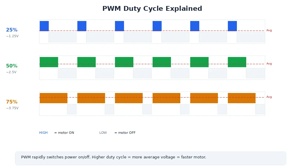
PWM: Pulse Width Modulation
How do you control the speed of the motor? You can't vary the voltage continuously — microcontrollers output digital signals (0V or 5V).
The solution is PWM (Pulse Width Modulation). You rapidly switch the voltage on and off. The duty cycle (percentage of time the signal is high) controls the average power.
100% duty cycle (full speed):
████████████████████████  (always on)

50% duty cycle (half speed):
████    ████    ████    ████

25% duty cycle (quarter speed):
██  ██  ██  ██  ██  ██  ██  ██

0% duty cycle (stopped):
                        (always off)
The motor's inductance smooths out the pulses, so the motor sees an average voltage proportional to the duty cycle.
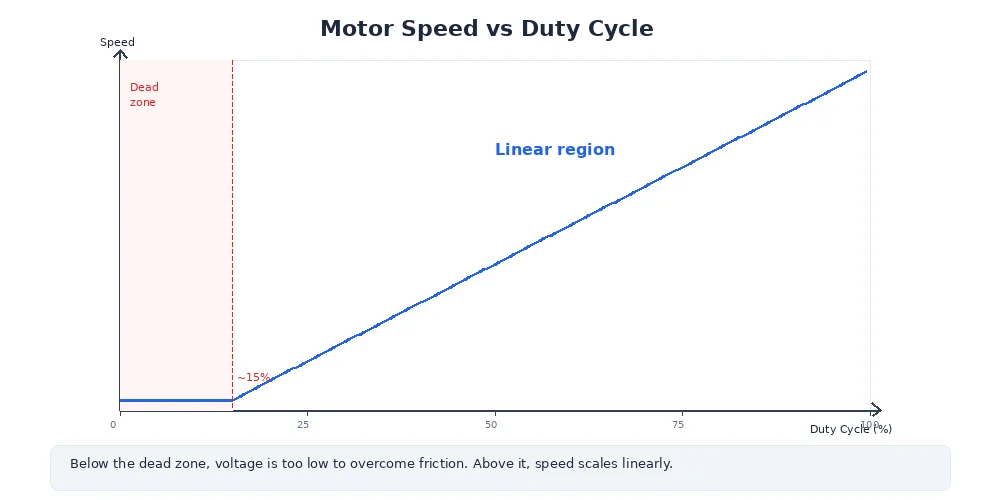
A typical PWM frequency for motors is 20-50 kHz — fast enough that the motor doesn't "feel" the individual pulses, but slow enough to minimize switching losses.
import RPi.GPIO as GPIO

# Set up PWM on pin 18
motor_pin = 18
GPIO.setup(motor_pin, GPIO.OUT)
pwm = GPIO.PWM(motor_pin, 1000)  # 1 kHz PWM frequency

# Set speed (0-100% duty cycle)
pwm.start(0)       # Start at 0%
pwm.ChangeDutyCycle(50)  # 50% power (half speed)
time.sleep(2)
pwm.ChangeDutyCycle(100) # 100% power (full speed)
time.sleep(2)
pwm.stop()         # Stop PWM
What's Next?
So far, we've been controlling individual motors or joints. But what if you want to control the robot's overall motion — like "drive forward at 0.5 m/s" or "turn left at 30 degrees/second"?
That's where velocity commands come in — and they require translating high-level motion goals into individual wheel speeds. We'll cover that in the next lesson.